| CPC G01L 19/147 (2013.01) [G01L 13/00 (2013.01); G01L 19/142 (2013.01)] | 6 Claims |

|
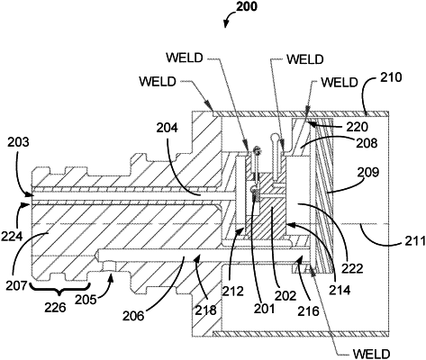
1. A differential pressure transducer assembly, comprising:
a header;
a front attachment port;
two or more header pins disposed perpendicular to a rotationally invariant axis of a front portion of the front attachment port of the differential pressure transducer assembly, each of the two or more header pins extending through a sidewall of the header and configured for electrical communication with a sensing element while being electrically isolated from the header;
a front adapter attached to a front portion of the header, the front adapter comprising a main channel configured to communicate with the front portion of the header;
a back adapter attached to a back portion of the header, the back adapter comprising a first portion of a reference channel in communication with a reference port opening in the front attachment port, wherein the front attachment port-comprises a second portion of the reference channel in communication with the first portion of the reference channel and in further communication with the port opening of the front attachment port, wherein the front attachment port is configured for mating with the front adapter; and
a cap attached to a back portion of the back adapter, the cap at least partially defining a reference cavity in communication with the first portion of the reference channel of the back adapter and the second portion of the reference channel of the front attachment port;
wherein:
the front adapter is welded to the front portion of the header;
the back adapter is welded to the back portion of the header;
a front portion of the front adapter is welded to the front portion of the front attachment port; and
the cap is welded to the back portion of the back adapter.
|