| CPC G01C 19/5762 (2013.01) [B81B 3/0021 (2013.01); G01C 19/5712 (2013.01); G01C 19/5726 (2013.01); G01C 19/5733 (2013.01); G01C 19/5769 (2013.01); B81B 2201/0242 (2013.01); B81B 2203/0163 (2013.01); B81B 2203/04 (2013.01); B81B 2207/012 (2013.01)] | 21 Claims |

|
1. A microelectromechanical system (MEMS) gyroscope, comprising:
a suspended spring-mass system located in a MEMS layer, wherein the suspended spring-mass system comprises a driven mass, and wherein the driven mass comprises:
at least one driven mass sense electrode responsive to a movement of the driven mass along a first axis; and
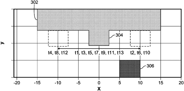
a drive amplitude electrode extending along a second axis that is perpendicular to the first axis;
at least one fixed drive sense electrode located in the MEMS layer adjacent to the at least one driven mass sense electrode and configured to capacitively engage with the driven mass sense electrode based on the movement of the driven mass along the first axis to generate a drive sense signal;
a fixed drive amplitude sense electrode located in the MEMS layer adjacent to the driven mass and configured to capacitively engage with the drive amplitude electrode based on the movement of the driven mass along the first axis; and
processing circuitry configured to receive a drive amplitude signal based on an overlap of the drive amplitude electrode and the fixed drive amplitude sense electrode, monitor a change in the received drive amplitude signal, determine a drive reference signal based on the monitored change of the received drive amplitude signal, and determine a drive motion of the driven mass based on the drive sense signal and the drive reference signal.
|