| CPC F25B 47/02 (2013.01) [F25B 13/00 (2013.01); F25B 41/20 (2021.01); F25B 49/02 (2013.01); F25B 2313/0231 (2013.01); F25B 2600/2513 (2013.01)] | 9 Claims |

|
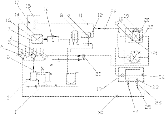
1. A non-stop defrosting multi-connected hot water system, comprising:
an outdoor unit comprising a compressor (1), a high-pressure pressure sensor (2), an oil separator (3), a first switching device (4), a second switching device (5), a third switching device (6), a fin type heat exchanger (7), a plate type heat exchanger (9), a first throttling device (10), a second throttling device (11), a third throttling device (12), an outdoor unit fan (14), and a phase-change heat storage module (15) with a heat storage function, and further comprising an outdoor unit ambient temperature sensor (16) configured to detect an ambient temperature of the outdoor unit in real time and a phase-change heat storage module temperature sensor (17) configured to detect a temperature of the phase-change heat storage module (15) in real time;
multi-connected indoor units, at least one indoor unit comprising an indoor unit heat exchanger (18), a fourth throttling device, an indoor unit fan (19), and an indoor unit ambient temperature sensor (20) configured to detect an ambient temperature of the indoor unit in real time, wherein the indoor unit heat exchanger (18) is further provided with an indoor unit heat exchanger central temperature sensor (21) and an indoor unit heat exchanger outlet temperature sensor (22) that are configured for real-time detection; and
a hydraulic module comprising a refrigerant water heat exchanger (23), a water pump (24), a water flow switch (25), a solenoid valve (26), and a water temperature detection sensor (27);
wherein working modes of the outdoor unit, the indoor unit, and the hydraulic module comprise a cooling mode, a heating mode, a standby mode, and a defrosting mode, and based on energy requirements of the working mode of the system, actions of components in the outdoor unit, the indoor unit, and the hydraulic module are respectively adjusted correspondingly:
when the indoor unit and the hydraulic module are in the standby mode, by checking a T4 temperature of the outdoor unit ambient temperature sensor (16), when the ambient temperature is lower than TS2, it is defaulted to enter a standby heat storage mode, the first switching device (4) is in a power-off state, the second switching device (5) is in a power-on state, and the third switching device (6) is in a power-off state;
when the indoor unit is in the cooling mode and the hydraulic module enters the heating mode, the phase-change heat storage module (15) starts to store heat, and at this time, the first switching device (4) is in the power-off state, the second switching device (5) is in the power-on state, and the third switching device (6) is in the power-off state;
when the outdoor unit enters the defrosting mode, the second throttling device (11) is opened to the maximum opening degree of 480P, the first switching device (4) is in the power-off state, the second switching device (5) is in the power-off state, and the third switching device (6) is in the power-on state;
when the indoor unit is in the standby mode and the hydraulic module enters the heating mode to make hot water, the phase-change heat storage module (15) starts to store heat, the first switching device (4) is in the power-off state, and the second switching device (5) is in the power-on state, and the third switching device (6) is in the power-off state;
when the outdoor unit enters the defrosting state, the second throttling device (11) is opened to the maximum opening degree of 480P, the first switching device (4) is in the power-off state, the second switching device (5) is in the power-off state, the third switching device (6) is in the power-on state, and the hydraulic module keeps heating;
when the indoor unit is in the heating mode and the hydraulic module is also making hot water, the phase-change heat storage module (15) starts to store heat, the first switching device (4) is in the power-on state, the second switching device (5) is in the power-on state, and the third switching device (6) is in the power-off state;
when the outdoor unit enters the defrosting mode, the second throttling device (11) is opened to the maximum opening degree of 480P, the first switching device (4) is in the power-on state, the second switching device (5) is in the power-off state, and the third switching device (6) is in the power-on state;
when the indoor unit is in the heating mode, the phase-change heat storage module (15) starts to store heat, and at this time, the first switching device (4) is in the power-on state, the second switching device (5) is in the power-on state, and the third switching device (6) is in the power-off state; and
when the outdoor unit enters the defrosting mode, the second throttling device (11) is opened to the maximum opening degree of 480P, the first switching device (4) is in the power-on state, the second switching device (5) is in the power-off state, the third switching device (6) is in the power-on state, and the operating state of an internal unit remains unchanged.
|