| CPC F16F 9/348 (2013.01) [F16F 9/368 (2013.01); F16F 9/5126 (2013.01); B60G 13/08 (2013.01); B60G 17/08 (2013.01); B60G 2202/24 (2013.01); B60G 2204/62 (2013.01); B60G 2206/41 (2013.01); B60G 2500/114 (2013.01); B60G 2800/162 (2013.01); F16F 9/061 (2013.01); F16F 2222/12 (2013.01); F16F 2228/066 (2013.01); F16F 2232/08 (2013.01); F16F 2234/02 (2013.01)] | 7 Claims |

|
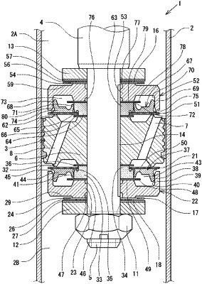
1. A shock absorber comprising:
a cylinder in which hydraulic fluid is contained in a sealed manner;
a piston that is slidably fitted in the cylinder;
a piston rod having a first end coupled to the piston and a second end extending outside the cylinder;
a main valve configured to generate a damping force by controlling a hydraulic fluid flow from an upstream chamber to a downstream chamber which is created when the piston moves in a first direction;
a back pressure chamber that is arranged in the downstream chamber and applies a back pressure acting onto the main valve in a valve-closing direction;
a seal mechanism that moves with motion of an outer peripheral portion of the main valve when the main valve is open, and defines the back pressure chamber; and
a back pressure introduction path for introducing the hydraulic fluid of the upstream chamber into the back pressure chamber,
wherein opening of the main valve is controlled by the back pressure of the back pressure chamber, and
the seal mechanism is configured to function as a valve that introduces into the back pressure chamber the hydraulic fluid in the chamber that becomes a downstream chamber when the piston moves in the first direction, when the piston moves in a second direction,
wherein the main valve is supported with an inner peripheral side not clamped, and
wherein the inner peripheral side of the main valve is provided with a blocking member that blocks a hydraulic fluid flow from the back pressure chamber into the upstream chamber which is created when the piston moves in the second direction.
|