| CPC F16D 3/12 (2013.01) [F02N 7/00 (2013.01); F16F 15/13469 (2013.01); F16H 45/02 (2013.01); F16F 2226/00 (2013.01); F16F 2228/001 (2013.01); F16F 2228/007 (2013.01); F16F 2232/02 (2013.01); F16F 2236/08 (2013.01); F16H 2045/0226 (2013.01)] | 19 Claims |

|
1. A transmission system including a damper device comprising:
an input element coupled to an engine via a clutch;
an output element coupled to an input shaft of a transmission; and
a plurality of elastic bodies disposed between the input element and the output element, wherein
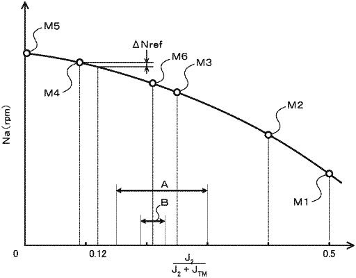
when a total moment of inertia of the output element and a rotation element that rotates integrally with the output element on the engine side with respect to the input shaft is J2, and when a total moment of inertia of all rotating members included between the input shaft and a differential gear coupled to an output shaft of the transmission is JTM, 0.12≤J2/(J2+JTM)≤0.55 is satisfied.
|