| CPC F04D 29/462 (2013.01) [F04D 17/10 (2013.01); F04D 27/0246 (2013.01); F04D 27/023 (2013.01); F04D 27/0207 (2013.01); F04D 27/0215 (2013.01); F04D 29/4213 (2013.01)] | 3 Claims |

|
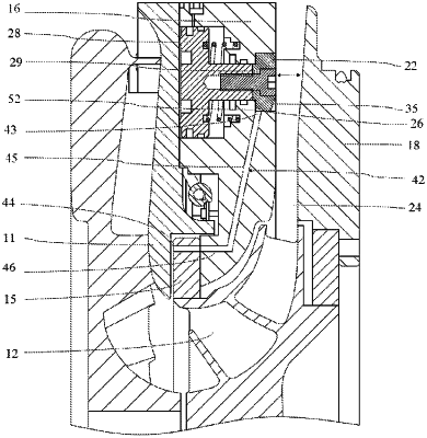
1. A centrifugal compressor, comprising:
an impeller (12) configured to suction a gas to be compressed;
a diffuser (13) disposed downstream of the impeller (12) to pressurize the gas, the diffuser (13) comprising a movable ring (22), a main passage (24) in which the gas flows past the ring (22), and an openable branch passage (26); and
a circulation loop (42) comprising an inlet (43) and an outlet (44), the outlet (44) being in communication with an inlet of the impeller (12);
wherein the branch passage (26) is disposed to be in communication with the main passage (24) and the circulation loop (42) when the ring (22) moves into the main passage (24) so that a portion of the gas in the main passage (24) passes through the circulation loop (42) and returns to the impeller (12) so as to be suctioned, and to be closed when the ring (22) is withdrawn from the main passage (24);
wherein at least a portion of the circulation loop (42) is formed by a chamber inside the centrifugal compressor that is close to the impeller (12), and the outlet of the circulation loop (42) is an outlet of the chamber.
|