| CPC F04C 18/0215 (2013.01) [F04C 18/0261 (2013.01); F04C 29/0007 (2013.01); F04C 29/042 (2013.01); F04C 29/12 (2013.01); F04C 29/128 (2013.01); F04C 2240/30 (2013.01); F04C 2250/102 (2013.01)] | 14 Claims |

|
1. A scroll compressor comprising:
a housing;
a motor provided in the housing;
a rotating shaft rotated by the motor;
an orbital scroll orbitally moved by the rotating shaft; and
a fixed scroll forming a compression chamber together with the orbital scroll, wherein the housing further comprises:
a center housing through which the rotating shaft passes;
a front housing forming a motor accommodating space in which the motor is accommodated; and
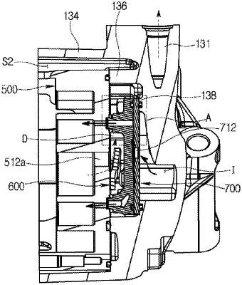
a rear housing having a discharge chamber accommodating a refrigerant discharged from the compression chamber, a discharge port guiding the refrigerant of the discharge chamber to an outside of the housing, an introduction port into which an intermediate pressure refrigerant is introduced from the outside of the housing, and an introduction chamber accommodating the refrigerant introduced through the introduction port, wherein the fixed scroll comprises an injection hole guiding the refrigerant of the introduction chamber to the compression chamber, wherein at least a portion of the introduction chamber is formed to be accommodated in the discharge chamber, and
wherein the rear housing further comprises:
a first annular wall located at the outermost side in the circumferential direction of the rear housing;
a second annular wall accommodated in the first annular wall and forming the discharge chamber; and
a third annular wall accommodated in the second annular wall and forming the introduction chamber.
|