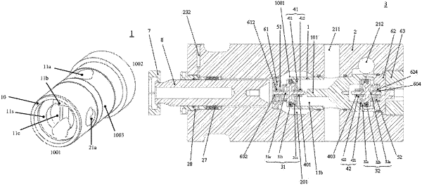
| CPC F04B 53/125 (2013.01) [F04B 19/22 (2013.01); F04B 53/1087 (2013.01); F04B 53/16 (2013.01)] | 19 Claims |

|
1. A fluid splitter, comprising:
a body, wherein the body has a shape of column, and the body comprises a first end, a second end, and a side surface connecting the first end and the second end;
a first opening, located at the side surface of the body;
a first cavity, located at the first end;
a first channel, communicated with the first opening and the first cavity, respectively, wherein the first channel extends from the first opening to the first cavity and is configured to allow fluid to flow therethrough;
a second opening, located at the side surface of the body;
a second cavity, located at the second end; and
a second channel, communicated with the second opening and the second cavity, respectively, wherein the second channel extends from the second opening to the second cavity and is configured to allow fluid to flow therethrough,
wherein the first opening is closer to the second end than the second opening, and the second opening is closer to the first end than the first opening.
|