| CPC F04B 45/0533 (2013.01) [F04B 43/073 (2013.01); F04B 45/043 (2013.01); F04B 45/053 (2013.01); F04B 45/0536 (2013.01); F04B 49/22 (2013.01); F04B 53/06 (2013.01); F04B 53/14 (2013.01); F04B 2201/0201 (2013.01); F04B 2201/0202 (2013.01); F04B 2205/05 (2013.01)] | 20 Claims |

|
1. A diaphragm compressor system, comprising:
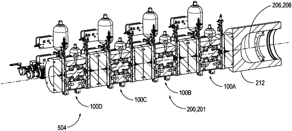
a plurality of compressor modules mounted in a stack configuration, each compressor module comprising:
a first compressor head and a second compressor head, each of the first and second compressor heads comprising:
a head cavity, and
a diaphragm mounted in the head cavity and dividing the head cavity into a work oil region and a process gas region,
the diaphragm configured to actuate from a first position to a second position during a discharge cycle to pressurize process gas in the process gas region from an inlet pressure to a discharge pressure, and discharge the pressurized process gas through the respective compressor head,
wherein the diaphragms of the first and second compressor heads of each compressor module are centered on a compressor axis;
a hydraulic drive configured to pressurize work oil and provide the pressurized work oil to the first and second compressor heads, the hydraulic drive comprising:
a hydraulic power unit configured to provide a variable-pressure supply of work oil to the hydraulic drive,
a plurality of pressure circuits comprising: a first pressure circuit of work oil at a first pressure, and a second pressure circuit of work oil at a second pressure,
a first diaphragm piston, wherein a first variable volume region is defined between the first diaphragm piston and the diaphragm of the first compressor head, and
a second diaphragm piston, wherein a second variable volume region is defined between the second diaphragm piston and the diaphragm of the second compressor head,
wherein, during a discharge cycle of a compressor head, the hydraulic drive is configured to drive the respective diaphragm piston toward the corresponding diaphragm compressor head, intensifying the work oil in the respective variable volume region to an intensified pressure, and actuating the diaphragm to the second position; and
a clamping mechanism configured to apply a clamping force to the first and second compressor head of each compressor module of the plurality of compressor modules, the clamping mechanism comprising a base plate and an end plate configured to be compressed on opposing sides of the plurality of compressor modules, wherein the plurality of compressor modules are configured such that the first or second compressor head of each compressor module not adjacent to the base plate or end plate contacts the first or second compressor head of an adjacent compressor module;
wherein the clamping mechanism is configured to increase a distance between the base plate and the end plate in response to thermal expansion of one or more compressor modules of the plurality of compressor modules, and
wherein the clamping mechanism is configured to apply the clamping force parallel to the compressor axis.
|