| CPC E21D 21/006 (2016.01) [E21D 21/008 (2013.01); E21D 21/0033 (2013.01)] | 7 Claims |

|
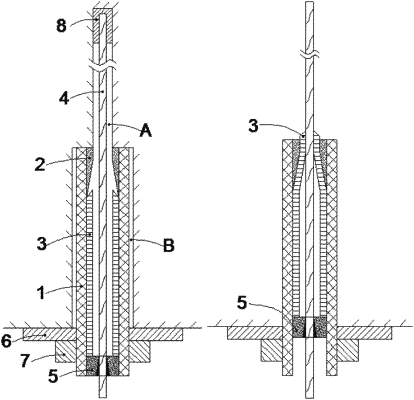
1. A construction method for a deformable anchor cable capable of being prestressed, wherein the anchor cable comprises an outer sleeve, a shrinkage pipe, an inner sleeve, a steel strand, an anchor and a tray; the strength of the inner sleeve is less than the strength of the shrinkage pipe; the shrinkage pipe comprises a necked section and an equal-diameter section that are sequentially connected from outside to inside; the outer diameter of the necked section remains unchanged, the inner diameter of the necked section gradually shrinks, and the outer diameter and inner diameter of the equal-diameter section remain unchanged;
construction comprises the following steps:
step 1, drilling an anchor hole in a rock mass to be supported, withdrawing a drill pipe after the drill pipe reaches the bottom, and then using a big diameter bit to ream and enlarge a hole mouth section, wherein the diameter of the anchor hole is greater than the diameter of the steel strand, and the diameter of the enlarged hole mouth section is matched with the diameter of the outer sleeve;
step 2, pushing the steel strand into the anchor hole rotatably, and fixing an inner end of the steel strand in the anchor hole by means of an anchoring agent;
step 3, fixing the shrinkage pipe to an inner end of the outer sleeve close to the depths of the drilled hole, then mounting a rubber plug on the inner end of the outer sleeve close to the depths of the drilled hole, then placing the outer sleeve into the enlarged section of the anchor hole and enabling the steel strand to pass through the outer sleeve;
step 4, enabling the inner sleeve to sleeve the steel strand, inserting the inner sleeve into the outer sleeve and enabling an inner end of the inner sleeve to make contact with a shrinkage end;
step 5, enabling an outer end of the steel strand to penetrate out of the anchor, and enabling the anchor to be sleeved by the outer sleeve and abut against an outer end of the inner sleeve;
step 6, enabling the tray to sleeve an exposed part of the outer sleeve, enabling an inner end of the tray to abut against the rock mass and an outer end of the tray to abut against a nut that is in threaded fit with an outer end of the outer sleeve, and tightening the nut to lock the tray; and
step 7, tensioning the steel strand by a tensioning apparatus to apply a prestress so as to meet design requirements, and applying a sufficient prestress to cause the inner sleeve to be squeezed out of the shrinkage pipe by a distance, thus completely blocking the shrinkage end and preventing moisture in the rock mass from entering the outer sleeve to cause corrosion.
|