| CPC E21B 17/03 (2013.01) [E21B 6/04 (2013.01)] | 20 Claims |

|
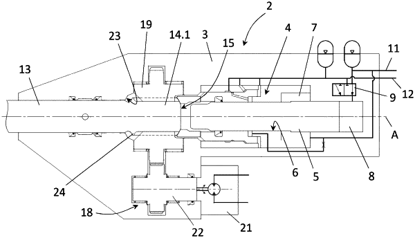
1. A rotary percussive hydraulic drill comprising:
a body,
a shank intended to be coupled to at least one drilling bar equipped with a tool, the shank including a coupling part comprising female coupling splines and male coupling splines which are angularly offset from each other with respect to an extension axis of the shank,
a striking piston slidably mounted inside the body along a striking axis and configured to strike the shank,
a rotation driving device which is configured to drive the shank in rotation about an axis of rotation substantially coincident with the striking axis, the rotation driving device comprising a coupling member disposed around the shank, the coupling member comprising male coupling splines and female coupling splines which are respectively rotatably coupled with the female coupling splines and male coupling splines of the shank,
a front abutment surface which is fixed with respect to the body, the front abutment surface being annular and extending around the shank, the shank being configured to abut against the front abutment surface so as to limit a displacement stroke of the shank forwards,
wherein the shank includes an annular bearing flange which is provided on an outer surface of the shank and which includes an annular bearing surface configured to abut against the front abutment surface, and wherein each of the female coupling splines and male coupling splines provided on the shank extends from the annular bearing flange and in a direction of the striking piston, each female coupling spline provided on the shank including a bottom surface and a connecting surface which connects the respective bottom surface to the annular bearing flange and which extends forwards away from the extension axis of the shank, the connecting surface of each female coupling spline provided on the shank being at least in part formed by a curved concave surface extending substantially in an extension direction of a respective female coupling spline and having a radius of curvature which is less than a radial height of each of the male coupling splines provided on the shank.
|