| CPC B60Q 3/66 (2017.02) [B60R 13/02 (2013.01); G02B 6/0043 (2013.01); G02B 6/0045 (2013.01); G02B 6/0088 (2013.01); B60Q 3/62 (2017.02); B60Q 3/64 (2017.02); G02B 6/004 (2013.01); G02B 6/0035 (2013.01); G02B 6/0036 (2013.01); G02B 6/0041 (2013.01); G02B 6/0075 (2013.01); G02B 6/0078 (2013.01)] | 13 Claims |
|
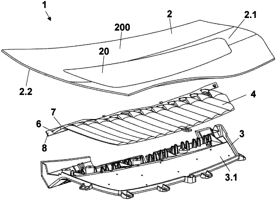
1. Backlit interior trim panel (1) for vehicle interior comprising:
a decorative cover (2) having a translucent backlit area (20) having a front decorative side (2.1) facing the vehicle interior and a back side (2.2) opposite to the front decorative side,
a supporting component (3),
a two-dimensional light guide (4) comprising multiple independent lighting areas (40), wherein said two-dimensional light guide (4) is placed between the decorative cover (2) and the supporting component (3), wherein the two-dimensional light guide (4) comprises:
a back light extracting surface (4.2),
a front light emission surface (4.1) configured to emit light to the back side (2.2) of the decorative cover (2) in correspondence with the translucent backlit area (20),
a plurality of lobed portions (4.3), wherein each lobed portion (4.3) extends longitudinally in a direction (1), wherein each lobed portion (4.3) comprises a curved surface (4.3.1) in correspondence with the front light emission surface (4.1) of the two-dimensional light guide (4), a flat surface (4.3.2) in correspondence with the back light extracting surface (4.2) of the two-dimensional light guide (4), two side surfaces (4.3.3), and two edges (4.3.4) defined at the ends of each lobed portion (4.3),
wherein the flat surface (4.3.2) of each lobed portion (4.3) defines a middle line (m) extending in the direction (l) and being between its both side surfaces (4.3.3),
wherein each lobed portion (4.3) comprises a variable thickness between its flat surface (4.3.2) and its curved surface (4.3.1) in a direction n perpendicular to the direction (l), in such a way that each lobed portion (4.3) has a minimum thickness emin, along its side surfaces (4.3.3) and a maximum thickness emax along the middle line (m),
wherein the lobed portions (4.3) are physically connected one another by its side surfaces (4.3.3),
wherein the lobed portions (4.3) are optically separated between them,
wherein each lobed portion (4.3) comprises a light source (6) configured to inject light inside said lobed portion (4.3) and wherein said light source (6) is in correspondence with any of its edges (4.3.4),
characterized in that,
each flat surface (4.3.2) comprises light extracting means (5) having a light extracting capacity increasing progressively as said extracting means (5) are separated from the light source (6) in the direction (l), and having a light extracting capacity decreasing progressively as said extracting means are separated from the middle line (m) in the direction (n), in such a way that each lobed portion (4.3) defines an independent lighting area (40) configured to emit homogenous light from its curved surface (4.3.1) over its whole surface, and in such a way that when two contiguous lobed portions (4.3) emit light having the same lighting parameters from their curved sides (4.3.1) and at the same time, said light emitted is substantially homogenous across an optical separation between said contiguous lobed portions (4.3).
|