| CPC B25J 15/065 (2013.01) [B25J 15/0616 (2013.01); B65G 49/05 (2013.01); G02B 5/1847 (2013.01); G02B 5/284 (2013.01)] | 7 Claims |

|
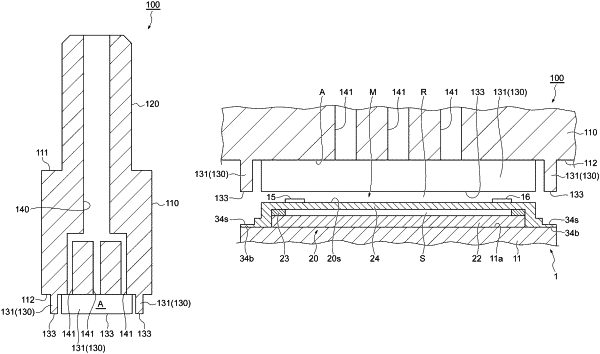
1. A suction method of performing suction of a Fabry-Perot interference filter including: a substrate; a laminated structure that is provided on the substrate and that includes a main surface facing a side opposite to the substrate; and a thinned portion that is located outside the laminated structure when viewed in a direction intersecting the main surface and that is recessed to a side of the substrate with respect to the main surface, by using a suction collet,
the method comprising:
a first step of arranging the suction collet so as to face the main surface;
a second step of bringing the suction collet into contact with the Fabry-Perot interference filter after the first step; and
a third step of suctioning the Fabry-Perot interference filter by using the suction collet after the second step,
wherein the suction collet includes: a main body having a surface provided with an opening for air intake; and a contact portion that is provided on the surface so as to protrude from the surface and that includes a contact surface,
the laminated structure is provided with a membrane structure including a first mirror portion and a second mirror portion facing each other via a gap and in which a distance from each other is variable and including a portion of the main surface,
in the first step, the suction collet is arranged such that the contact surface faces a bottom surface of the thinned portion,
in the second step, the contact surface is brought into contact with the bottom surface while forming a space between the surface and the main surface, and
in the third step, an inside of the space is exhausted by the air intake through the opening.
|