| CPC B05B 1/34 (2013.01) [B05B 9/01 (2013.01); B05B 12/0024 (2018.08)] | 21 Claims |

|
1. A spray tip comprising:
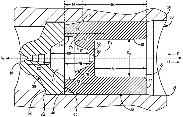
a cylindrical body having a through hole oriented along a fluid flow axis;
a spray outlet piece located in the through hole, the spray outlet piece having an outlet aperture configured to atomize and output a spray fluid, the spray outlet piece including a domed portion and the outlet aperture having a cat-eye shape and extending into the domed portion;
an upstream chamber piece located in the through hole, the upstream chamber piece comprising:
an internal aperture wall comprising an upstream surface and a downstream surface; and
an aperture through the wall, the aperture comprising:
an inlet orifice opening flush with the upstream surface and having a first diameter;
an outlet orifice opening located at the downstream surface and having a second diameter different from the first diameter;
an annular inner surface that is linearly sloped along its entire length between the inlet orifice opening and the outlet orifice opening of the aperture wall;
an annular inlet corner defining the inlet orifice opening, the annular inlet corner defined as a smaller of two angles taken between the upstream surface of the aperture wall and the annular inner surface of the aperture; and
an annular outlet corner defining the outlet orifice opening, the annular outlet corner defined as a smaller of two angles taken between the downstream surface of the aperture wall and the annular inner surface;
wherein one of the annular inlet corner or the annular outlet corner is less than 90 degrees; and
a turbulation chamber defined by the spray outlet piece and the upstream chamber piece;
wherein the spray tip is rotatable between a spray position and a reversed position in which a direction of flow through the spray tip is reversed for unclogging of the spray tip; and
wherein in the spray position, the upstream chamber piece is disposed upstream of the spray outlet piece, and the outlet aperture is disposed downstream of the turbulation chamber and is configured to receive a flow of fluid from the turbulation chamber.
|