| CPC A61F 2/89 (2013.01) [A61F 2/07 (2013.01); A61F 2/915 (2013.01); A61F 2002/072 (2013.01); A61F 2002/91541 (2013.01); A61F 2002/91583 (2013.01); Y10T 29/49826 (2015.01)] | 18 Claims |

|
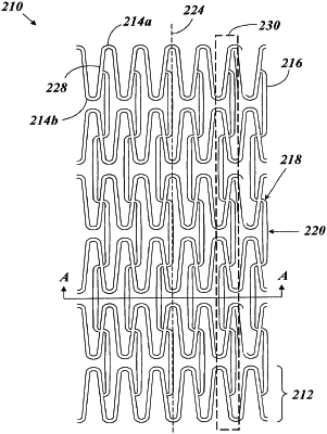
1. A method of manufacturing a stent device, the method comprising:
providing a plurality of generally cylindrical rings each formed by a plurality of substantially repeating bent segments, each of the plurality of bent segments comprising one substantial peak, one substantial valley, and a transition region leading between the one substantial peak and the one substantial valley, each bent segment having a midpoint on the transition region substantially midway between the one substantial peak and the one substantial valley, the plurality of rings being arranged in a series along a longitudinal axis in such a way that the one substantial peak and the one substantial valley of each bent segment of each ring in the series is substantially a mirror image of one substantial peak and one substantial valley of a corresponding curved segment in an immediately adjacent ring; and
providing a plurality of interconnecting members, each of the plurality of interconnecting members comprising:
a first coupling end;
a second coupling end opposite the first coupling end; and
an elongate portion extending between the first coupling end and the second coupling end, wherein the first coupling end, the elongate portion, and the second coupling end combine in a first orientation or a second orientation that is substantially a mirror image of the first orientation;
wherein the first coupling end intersects with the midpoint of the transition region of a bent segment of a ring of the plurality of rings and the second coupling end intersects with the midpoint of a bent segment of a different and immediately adjacent ring of the plurality of rings;
wherein each of the plurality of interconnecting members has a fusiform shape in which a width of each interconnecting member at the center of the elongate portion is the widest position of each interconnecting member, wherein each interconnecting member narrows along its length in both directions from the center of the elongate portion, and wherein the first coupling end forms a first end of the fusiform shape and the second coupling end forms a second end of the fusiform shape;
wherein the plurality of interconnecting members is arranged in rows extending longitudinally along the device; and
wherein along each of the rows the interconnecting members alternate with each consecutive occurrence between the first orientation and the second orientation.
|