| CPC A24F 40/51 (2020.01) [A24F 40/40 (2020.01); A24F 40/50 (2020.01); A24F 40/60 (2020.01); A24F 40/10 (2020.01)] | 21 Claims |

|
1. A control body for an electronic smoking article, the control body comprising:
an outer housing having a longitudinal axis extending therethrough;
an electrical power source positioned within the outer housing;
an electronic circuit board positioned within the outer housing;
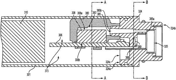
a pressure sensor comprising a first end and a second end, the pressure sensor being attached to the electronic circuit board such that the second end of the pressure sensor is adjacent the electronic circuit board;
a sealing member arranged so as to form a seal substantially surrounding a perimeter of the pressure sensor, the sealing member being configured such that the first end of the pressure sensor is positioned in a pressure reduction space and the second end of the pressure sensor is positioned in a normal pressure space within the outer housing
a distal end;
a proximal end configured to include a wall separating an interior of the outer housing from a cavity configured to releasably engage a cartridge; and
an air flow pathway arranged so that air enters the cavity and passes from the cavity into the cartridge without first passing through the interior of the housing,
wherein the wall separating the interior of the outer housing from the cavity includes at least one pressure channel extending between a first end that is in fluid communication with the cavity and a second end that opens through the wall to be in fluid communication with the pressure reduction space and the first end of the pressure sensor such that a pressure drop in the cavity is communicated through the pressure channel to the pressure reduction space and the first end of the pressure sensor.
|