| CPC H02J 3/381 (2013.01) [G05B 19/042 (2013.01); H02J 2203/20 (2020.01); H02J 2300/24 (2020.01)] | 9 Claims |

|
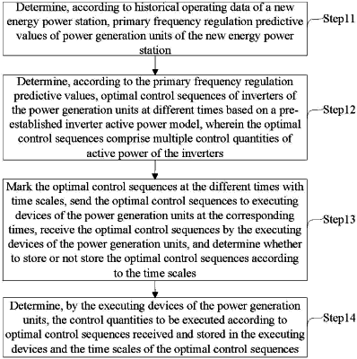
1. A networked control method for primary frequency regulation of a new energy power station, comprising:
determining, according to historical operating data of a new energy power station, primary frequency regulation predictive values of power generation units of the new energy power station;
determining, according to the primary frequency regulation predictive values, optimal control sequences of inverters of the power generation units at different times based on a pre-established inverter active power model, wherein the optimal control sequences comprise multiple control quantities of active power of the inverters;
marking the optimal control sequences at the different times with time scales, sending the optimal control sequences to executing devices of the power generation units at the corresponding times, receiving the optimal control sequences by the executing devices of the power generation units, and determining whether to store or not store the optimal control sequences according to the time scales; and
determining, by the executing devices of the power generation units, the control quantities to be executed according to optimal control sequences received and stored in the executing devices and the time scales of the optimal control sequences, and executing the determined control quantities to control the inverters of the power generation units to regulate a frequency of the new energy power station;
wherein the inverter active power model is established through the following steps:
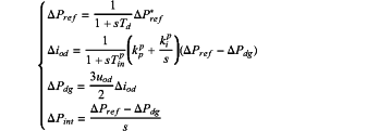
establishing an equivalent mathematical model of active power output by the inverters in a PQ mode:
 wherein, ΔPref* is a difference between reference power and present power of the inverters, ΔPref is a difference between actual reference power and the present power of the inverters, Td is a delay from receipt of a control instruction by the inverters to execution of the control instruction by the inverters, Δiod is a difference between a d-axis current component at a present time and a d-axis current component at a previous time of the inverters, Tinp is a time constant of an inner current loop of the active power, kpp and kip are a proportional coefficient and an integral coefficient of an outer power loop PI controller respectively, ΔPdg is a difference between output power at the present time and output power at the previous time of the inverters, uod is a d-axis component of output port voltage of the inverters, ΔPint is an integral of a difference between ΔPref and ΔPdg, and s is a Laplace operator;
establishing a state-space model of the active power output by the inverters based on the equivalent mathematical model:
Δxcp=AcpΔxcp+BcpΔucp
wherein, Δxcp=[ΔPdgΔPintΔiodΔPref]T,
 discretizing Δxcp=AcpΔxcp+BcpΔucp to obtain a mathematical model of the active power output by the inverters in a discrete time:
x(k+1)=Ax(k)+Bu(k)
wherein, x(k)=[ΔPdg(k)ΔPint(k)Δiod(k)ΔPref(k)]T, ΔPdg(k) is a difference between output power at a time k and output power at a previous time of the inverters, Δiod(k) is a difference between a d-axis current component at the time k and the d-axis current component at the previous time of the inverters, ΔPref(k) is a difference between the actual reference power and the power at the time k of the inverters, ΔPint(k) is an integral of a difference between ΔPref(k) and ΔPdg(k), u(k)=[ΔPref*(k)], ΔPref*(k) is a difference between the reference power and the power at the time k of the inverters,
 is a sampling time.
|