| CPC H01Q 9/16 (2013.01) [H01Q 9/065 (2013.01); H01Q 21/0006 (2013.01); H01Q 21/062 (2013.01)] | 14 Claims |

|
1. An antenna array, comprising
a plurality of antennas forming an array,
a single common ground plane coupled to each of the plurality of antennas, wherein each of the antennas is disposed above the ground plane,
a feed portion associated with each of the plurality of antennas and disposed below the ground plane, and
a dielectric top cover coupled to the plurality of antennas,
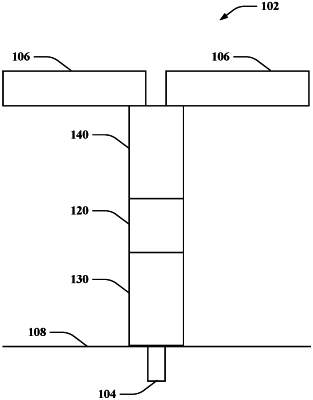
wherein each of the antennas of the plurality of antennas includes a pair of radiating elements and an impedance matching network coupled to the radiating elements, wherein the impedance matching network includes
a first impedance transformer connected to the feed portion,
a balun directly connected at one end to the first impedance transformer, wherein the balun has a central inner portion and a pair of opposed outer portions, and
a second impedance transformer directly connected to the other end of the balun and to the radiator such that the balun is disposed between the first impedance transformer and the second impedance transformer,
wherein the feed portion, the first impedance transformer, the balun and the second impedance transformer are connected and arranged in series,
wherein the first impedance transformer includes a plurality of microstrip lines, wherein the plurality of microstrip lines includes a central conductor disposed between first and second edge conductors, wherein the first and second edge conductors have a relatively tapered shape and are generally the same size, and
wherein the central conductor is coupled to the central inner portion of the balun and the first and second edge conductors are coupled respectively to each of the opposed outer portions of the balun.
|