| CPC H01M 10/0587 (2013.01) [H01M 10/0431 (2013.01); H01M 50/10 (2021.01); H01M 50/103 (2021.01); H01M 50/116 (2021.01); H01M 50/119 (2021.01); H01M 50/20 (2021.01); H01M 50/209 (2021.01); H01M 50/50 (2021.01); H01M 50/502 (2021.01); H01M 50/507 (2021.01); H01M 50/528 (2021.01); H01M 50/533 (2021.01); H01M 50/538 (2021.01); H01M 2220/20 (2013.01)] | 2 Claims |

|
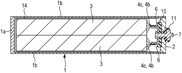
1. A prismatic secondary battery comprising:
a first flat-shaped winding electrode body in which a first positive electrode plate and a first negative electrode plate are wound with a first separator interposed therebetween;
a second flat-shaped winding electrode body in which a second positive electrode plate and a second negative electrode plate are wound with a second separator interposed therebetween;
a prismatic outer body that has an opening and a bottom and that houses the first flat-shaped winding electrode body and the second flat-shaped winding electrode body;
a sealing plate that seals the opening;
a positive electrode terminal that is electrically connected to the first positive electrode plate and the second positive electrode plate and attached to the sealing plate;
a positive electrode current collector that electrically connects the first positive electrode plate and the second positive electrode plate and the positive electrode terminal;
a negative electrode terminal that is electrically connected to the first negative electrode plate and the second negative electrode plate and attached to the sealing plate; and
a negative electrode current collector that electrically connects the first negative electrode plate and the second negative electrode plate and the negative electrode terminal,
wherein the first flat-shaped winding electrode body includes a plurality of first positive electrode tab portions and a plurality of first negative electrode tab portions at one end in a direction in which a winding axis of the first flat-shaped winding electrode body extends, and
wherein the second flat-shaped winding electrode body includes a plurality of second positive electrode tab portions and a plurality of second negative electrode tab portions at one end in a direction in which a winding axis of the second flat-shaped winding electrode body extends,
the first flat-shaped winding electrode body and the second flat-shaped winding electrode body are housed in the prismatic outer body so that the winding axis of the first flat-shaped winding electrode body and the winding axis of the second flat-shaped winding electrode body are disposed in a direction substantially perpendicular to the sealing plate,
the plurality of first positive electrode tab portions and the plurality of first negative electrode tab portions are located on one end of the first flat-shaped winding electrode body closer to the sealing plate than the other end, and
the plurality of second positive electrode tab portions and the plurality of second negative electrode tab portions are located on one end of the second flat-shaped winding electrode body closer to the sealing plate than the other end,
wherein the negative electrode current collector includes a first connecting portion connected to the negative electrode terminal, and a second connecting portion connected to the plurality of the first negative electrode tab portions,
the first connecting portion is spaced away from the second connecting portion in a longitudinal direction of the sealing plate.
|