| CPC H01H 33/662 (2013.01) [H01H 33/664 (2013.01)] | 4 Claims |

|
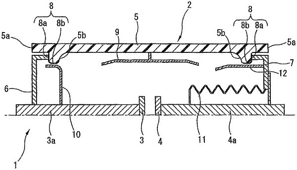
1. A vacuum interrupter, comprising:
a vacuum container in which both end portions of a cylindrical insulating tube are hermetically sealed by end plates;
a pair of electrodes provided in the vacuum container such that the pair of electrodes is capable of making separation from each other and contact with each other;
a projection portion that projects from the end portion of the insulating tube in an axial direction of the insulating tube, the projection portion being formed along an outer periphery of the insulating tube;
an end plate joining portion that is provided to project from a base end portion of the projection portion inwardly in a radial direction of the insulating tube such that a radial thickness at the end plate joining portion of the insulating tube is thicker than a radial thickness of other parts of the insulating tube; and
a metallized layer provided at a surface of the end plate joining portion, the end plate being joined to the metallized layer.
|