| CPC G04B 19/02 (2013.01) [G04B 9/005 (2013.01); G04B 13/001 (2013.01); G04B 13/007 (2013.01); G04B 13/008 (2013.01); G04B 13/021 (2013.01); G04B 19/042 (2013.01); G04B 19/048 (2013.01); G04B 19/082 (2013.01); G04B 45/0061 (2013.01); G04B 13/02 (2013.01)] | 21 Claims |

|
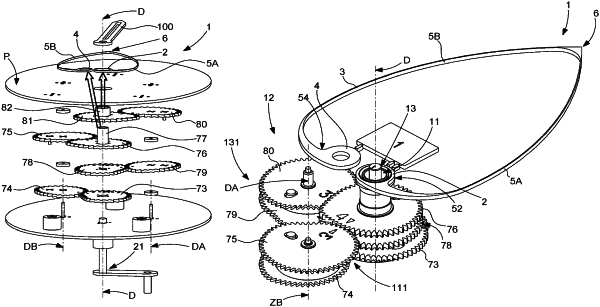
1. A variable-geometry timepiece display mechanism comprising:
at least one resilient hand which comprises a first drive pipe integral with a first end of a flexible strip, and a second drive pipe integral with another end of said flexible strip, and which comprises a display index or tip which, in an unstressed free state of said resilient hand wherein both said first pipe and said second pipe are not subjected to any stress and are remote from one another, is remote from said first pipe and from said second pipe, the operating position of said resilient hand being a stressed position where said first pipe and said second pipe are coaxial to one another about an output axis; and
first means for driving said first pipe about said output axis, and second means for driving said second pipe about said output axis, said first drive means and second drive means being arranged so as to deform said flexible strip by varying the angular position of said second pipe relative to the angular position of said first pipe about said output axis, and so as to vary the radial position of said display index or tip relative to said output axis, whereby said first drive means and/or second stressing means comprise an accelerator or decelerator device, which is arranged such that it accelerates, or stabilizes the speed of, or slows down at least said first pipe and/or said second pipe over at least part of the angular travel thereof,
wherein said accelerator or decelerator device comprises a first shaped gear train including a first shaped wheel driven by a first cannon-pinion, the first shaped wheel gears with a second shaped wheel that idles about a first axis, the second shaped wheel being pivotably integral with a third shaped wheel, the third shaped wheel gears with a fourth shaped wheel that pivots about the output axis and comprises a second cannon-pinion attached to the first pipe,
wherein said accelerator or decelerator device comprises a second shaped gear train including a fifth shaped wheel driven by the first cannon-pinion, the fifth shaped wheel gears with a sixth shaped wheel that idles about a second axis, the sixth shaped wheel being pivotably integral with a seventh shaped wheel, the seventh shaped wheel gears with an eighth shaped wheel that pivots about the output axis and comprises a third cannon-pinion attached to the second pipe, and
wherein each of the first through eighth shaped wheels is non axisymmetric.
|