| CPC G01R 31/282 (2013.01) [G01R 1/0416 (2013.01); G01R 21/07 (2013.01)] | 17 Claims |

|
1. An electronic monitoring circuit for detecting a variation in a power or a current absorbed by an electronic circuit under test, the electronic monitoring circuit comprising:
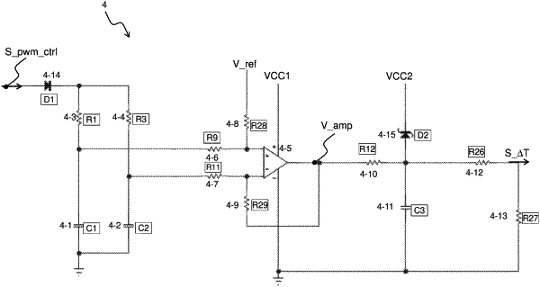
an input terminal configured to receive a pulse-width modulation control signal, wherein said control signal is configured to control opening and closing of at least one power switch of a switch mode power supply of the electronic circuit under test;
a resistor having a first terminal connected to the input terminal;
a capacitor having a first terminal connected to a second terminal of the resistor and having a second terminal connected to a low reference voltage; and
an output terminal configured to generate an output signal as a function of value of the voltage drop between the terminals of the capacitor, said output signal being representative of a variation in the pulse width of the pulse-width modulation control signal, wherein said variation in the pulse width is a function of power or current absorbed by the electronic circuit under test,
the electronic monitoring circuit further comprising:
a further resistor having a first terminal connected to the input terminal;
a further capacitor having a first terminal connected to a second terminal of the further resistor and having a second terminal connected to the low reference voltage;
wherein:
the output terminal of the electronic monitoring circuit is configured to generate the output signal as a function of the difference between the value of the voltage drop between the terminals of the capacitor and the value of the voltage drop between the terminals of the further capacitor;
and wherein, alternatively:
the resistance value is equal for said resistor and said further resistor and the capacitance value differs between said capacitor and said further capacitor;
the resistance value differs between said resistor and said further resistor and the capacitance value is equal for said capacitor and said further capacitor.
|