| CPC G01P 15/0802 (2013.01) [B81B 3/001 (2013.01); B81B 3/0051 (2013.01); G01P 15/125 (2013.01); B81B 2201/0235 (2013.01); B81B 2203/0163 (2013.01); B81B 2203/04 (2013.01); G01P 2015/0831 (2013.01); G01P 2015/0862 (2013.01); G01P 2015/0871 (2013.01)] | 8 Claims |

|
1. A micromechanical structure, comprising:
a substrate;
a seismic mass movable with respect to the substrate;
a detection structure; and
a main spring, the seismic mass being connected to the substrate using the main spring;
wherein a first direction and a second direction perpendicular to the first direction defining a main extension plane of the substrate;
wherein the detection structure is configured to detect a deflection of the seismic mass, the detection structure including an electrode structure, the electrode structure including first electrodes mounted at the seismic mass and second electrodes mounted at the substrate, the first electrodes and the second electrodes having a two-dimensional extension in the first direction and in the second direction;
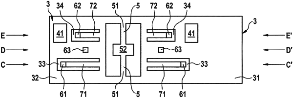
wherein the micromechanical structure has a graduated stop structure including a first spring stop, a second spring stop, and a fixed stop, the stop structure being configured in such a way that initially the first spring stop comes into mechanical contact with the substrate during a movement of at least one portion of the seismic mass in a third direction, which is perpendicular to the first direction and to the second direction, beyond an operating range, thereafter, the second spring stop comes into mechanical contact with the substrate during a further movement of at least one portion of the seismic mass in the third direction, and, thereafter, the fixed stop comes into mechanical contact with the substrate during a further movement of at least one portion of the seismic mass in the third direction,
wherein the first spring stop and the second spring stop are situated one behind the other in the second direction,
wherein the main spring includes a torsion spring, and wherein the detection structure is configured to detect a rotary deflection of the seismic mass about a rotation axis, the rotation axis being situated in the second direction,
wherein the fixed stop has a greater distance to the torsion spring than the first spring stop with respect to the first direction and the first spring stop has a greater distance to the torsion spring than the second spring stop with respect to the first direction.
|