| CPC G01F 1/36 (2013.01) [G01F 15/005 (2013.01)] | 17 Claims |
|
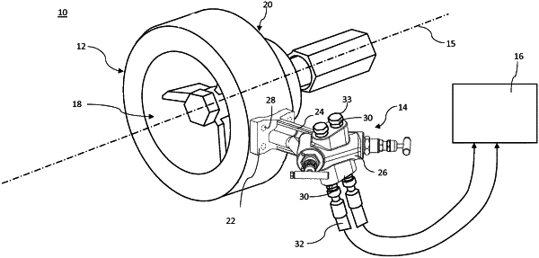
1. A differential pressure metering apparatus comprising a manifold for fluidically coupling impulse lines for a differential pressure meter to measurement ports of a flow restrictor pipe section having a longitudinal pipe axis, the manifold comprising:
a rigid body comprising a base for mounting to the flow restrictor pipe section, and an arm extending from the base to an impulse attachment portion for coupling to two impulse lines;
a high pressure channel extending through the rigid body from a high pressure inlet port to a high pressure outlet T-junction in the impulse attachment portion, the high pressure outlet T-junction having opposing first and second high pressure outlet ports each defining an impulse line extension direction along which an impulse line extends when connected to the respective port;
a low pressure channel extending through the rigid body from a low pressure inlet port to a low pressure outlet T-junction in the impulse attachment portion, the low pressure outlet T-junction having opposing first and second low pressure outlet ports each defining an impulse line extension direction along which an impulse line extends when connected to the respective port;
whereby the manifold is configured to be mounted to the flow restrictor pipe section in a wet-line configuration:
when the longitudinal pipe axis of the flow restrictor pipe section extends horizontally; and
when the longitudinal pipe axis of the flow restrictor pipe section extends vertically;
wherein in the wet-line configuration, the first high pressure outlet port and the first low pressure outlet port define impulse line extension directions having a downward component, and the second high pressure outlet port and the second low pressure outlet port define impulse line extension directions having an upward component.
|