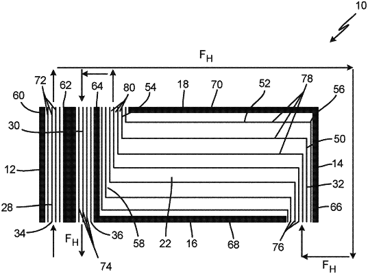
| CPC F28D 9/0068 (2013.01) [F28D 9/0093 (2013.01); F28F 3/025 (2013.01)] | 11 Claims |

|
1. A heat exchanger comprising:
a first end opposite a second end;
a first side opposite a second side, wherein the first side and the second side extend from the first end to the second end;
a first layer comprising:
an inlet at the first end of the heat exchanger; and
an outlet at the second end of the heat exchanger; and
a second layer comprising:
a first passage at the first end of the heat exchanger and extending from the first side to the second side;
a second passage adjacent to the first passage, wherein the second passage extends from the first side to the second side and wherein the second layer further comprises:
a first closure bar at the first end and extending from the first side to the second side;
a second closure bar extending from the first side to the second side between the first passage and the second passage;
a third closure bar extending from the first side to the second side between the second passage and the third portion of the third passage;
a fourth closure bar at the second end and extending from the first side to the second side;
a fifth closure bar extending from the third closure bar toward the fourth closure bar on the first side;
a sixth closure bar extending from the fourth closure bar toward the third closure bar on the second side;
a first plurality of fins in the first passage extending in a direction parallel to the second closure bar;
a second plurality of fins in the second passage and extending in the direction parallel to the second closure bar;
a third plurality of fins in the first portion of the third passage and extending in a direction parallel to the fourth closure bar;
a fourth plurality of fins in the second portion of the third passage and extending in a direction parallel to the fifth closure bar and the sixth closure bar; and
a fifth plurality of fins in the third portion of the third passage and extending in a direction parallel to the third closure bar; and
a third passage extending from the second end toward the second passage, wherein the first passage is fluidically connected to the third passage proximate the second end, and wherein the third passage is fluidically connected to the second passage, wherein the third passage comprises:
a first portion extending from the first side to the second side;
a second portion extending from the first portion toward the first end;
a third portion between the second passage and the second portion, wherein the third portion extends from the first side to the second side;
a first turn between the first portion and the second portion; and
a second turn between the second portion and the third portion,
wherein the first passage is fluidically upstream to the first portion of the third passage, and
wherein the third portion of the third passage is fluidically upstream with the second passage.
|