| CPC F25B 30/02 (2013.01) [F25B 29/003 (2013.01); F25B 41/20 (2021.01); F25B 41/26 (2021.01); F25B 2300/00 (2013.01); F25B 2313/0292 (2013.01)] | 15 Claims |

|
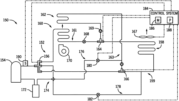
1. A heat pump system, comprising:
a refrigerant circuit comprising a compressor, a reversing valve, a first heat exchanger, a second heat exchanger, a reheat heat exchanger, a first three-way valve, and a second three-way valve,
wherein the reversing valve is configured to receive refrigerant from the compressor and adjust between a first configuration to direct the refrigerant toward the first three-way valve and a second configuration to direct the refrigerant toward the first heat exchanger,
wherein the first three-way valve is configured to adjust between a first position to direct the refrigerant between the reversing valve and the second heat exchanger and a second position to direct the refrigerant from the reversing valve to the reheat heat exchanger, and
wherein the second three-way valve is configured to adjust between a third position to direct the refrigerant between the first heat exchanger and the second heat exchanger and a fourth position to block flow of the refrigerant between the first heat exchanger and the second heat exchanger.
|