| CPC F23R 3/002 (2013.01) [F23R 3/005 (2013.01); F02C 3/04 (2013.01); F05D 2240/35 (2013.01); F05D 2260/2214 (2013.01); F23M 5/085 (2013.01); F23R 2900/03043 (2013.01)] | 16 Claims |

|
1. A system, comprising:
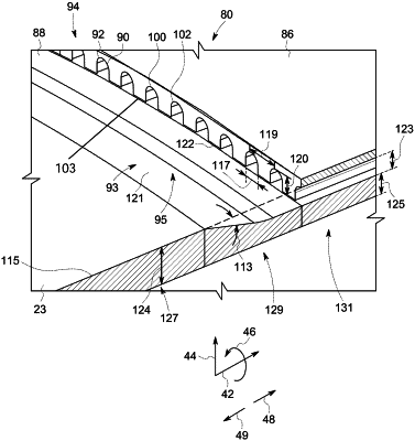
a combustor liner disposed about a combustion chamber of a combustor of a gas turbine system, wherein the combustor is configured to surround an aft end portion of the combustor liner with an upstream end portion of a transition piece, the combustor is configured to surround the combustor liner and the transition piece with a flow sleeve to define an intermediate flow passage, the intermediate flow passage is configured to direct a flow in an upstream direction relative to a downstream direction of a main flow of combustion gas through the combustor, and the aft end portion of the combustor liner comprises:
an inner wall portion exposed to the combustion chamber;
an outer wall portion disposed about the inner wall portion; and
a plurality of channels between the inner and outer wall portions of the combustor liner, wherein each channel of the plurality of channels is configured to direct a coolant flow in a flow direction along the combustor liner to convectively cool the combustor liner between an inlet and an outlet of the respective channel of the plurality of channels, the flow direction is oriented in the downstream direction of the main flow of combustion gas through the combustor, the inner and outer wall portions define the plurality of channels between the inlet and the outlet of each channel of the plurality of channels, each channel of the plurality of channels is recessed into a radially inner surface of the outer wall portion, the inlet of each channel of the plurality of channels is disposed in an axially facing surface at an upstream axial terminal end of the outer wall portion relative to the coolant flow, the outer wall portion terminates at the upstream axial terminal end, and each channel of the plurality of channels extends axially downstream of the inlet at a radial depth less than a radial thickness of the outer wall portion; and
an inlet guide disposed directly upstream from the inlets of the plurality of channels and the upstream axial terminal end of the outer wall portion, wherein the inlet guide comprises:
a ramp in the inner wall portion of the combustor liner and extending circumferentially about a central axis of the combustor liner about an entire circumference of the combustor liner, wherein the ramp comprises an angled surface having an angle defined by a decreasing thickness of the inner wall portion from a first thickness to a second thickness in the downstream direction toward the inlets of the plurality of channels; and
an opening extending circumferentially about the entire circumference of the combustor liner along the ramp within the intermediate flow passage between the combustor liner and the flow sleeve;
wherein the combustor excludes radial impingement openings directed radially inward toward a flow path of the coolant flow over an axial distance along the ramp, into the inlets, and through the plurality of channels; and
wherein a surface of the inner wall portion facing the combustion chamber is at a single, constant radial distance with respect to the central axis of the combustor liner over the axial distance along the ramp, into the inlets, and through the plurality of channels.
|