| CPC F04D 29/056 (2013.01) [F04D 17/10 (2013.01); F04D 25/0606 (2013.01); F04D 29/053 (2013.01); F04D 29/5806 (2013.01); F05D 2240/50 (2013.01); F05D 2240/60 (2013.01)] | 5 Claims |

|
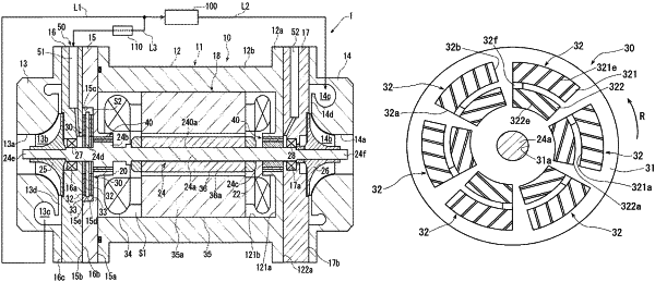
1. A turbo fluid machine comprising:
a rotary shaft configured to rotate in one rotational direction about an axis of the rotary shaft;
a thrust collar having a plate-like shape and formed on the rotary shaft such that the thrust collar extends from a peripheral surface of the rotary shaft in a radial direction of the rotary shaft, the thrust collar being rotatable together with the rotary shaft;
an operating part configured to rotate together with the rotary shaft to compress and discharge a fluid;
a housing accommodating the rotary shaft and the operating part; and
a thrust foil bearing supporting the rotary shaft in an axial direction of the rotary shaft such that the rotary shaft is rotatable relative to the housing, wherein
the thrust foil bearing includes:
a bearing housing having an insertion hole through which the rotary shaft is inserted and facing the thrust collar in the axial direction;
a plurality of bump foils attached on an end face of the bearing housing adjacent to the thrust collar, and the bump foils being disposed alongside around the insertion hole; and
a plurality of top foils each formed of an elastic thin plate and having opposite surfaces, one of the opposite surfaces serving as a bearing surface that faces the thrust collar, the other of the opposite surfaces being elastically supported by a corresponding bump foil of the plurality of bump foils,
each of the bump foils is formed of an elastic thin plate having a corrugated shape in which ridges of projections projected toward the thrust collar are arranged in a circumferential direction of the rotary shaft,
each of the bump foils is divided into an outer peripheral foil and an inner peripheral foil arranged respectively on an outer peripheral side and an inner peripheral side of the bump foil in the radial direction of the rotary shaft,
the ridges on the outer peripheral foil are inclined in the other rotational direction of the rotary shaft while extending from an edge of the outer peripheral foil adjacent to the inner peripheral side toward the outer peripheral side, and
the ridges on the inner peripheral foil are inclined in the other rotational direction of the rotary shaft while extending from an edge of the inner peripheral foil adjacent to the outer peripheral side toward the inner peripheral side.
|