| CPC F04C 14/04 (2013.01) [F01C 20/04 (2013.01); F04C 2/102 (2013.01); F04C 15/0065 (2013.01)] | 14 Claims |

|
1. A reversible gerotor pump system, comprising
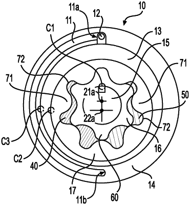
a cylindrical housing comprising a slot of 180 degree along a periphery of the housing, and the slot being defined by a first end at top and a second end at bottom,
an eccentric ring positioned within the housing with a radial clearance C3 between the eccentric ring and the housing,
a locking pin being fixed to the eccentric ring and movably engaged between the first end and the second end in the slot,
an outer rotor positioned within the eccentric ring with a radial clearance C2 between the eccentric ring and the outer rotor, the outer rotor being eccentric with the eccentric ring and comprising a plurality of internal teeth with recesses between adjacent teeth,
an inner rotor positioned within the outer rotor, the inner rotor comprising a plurality of external teeth, wherein at least a portion of the external teeth of the inner rotor are engaged with at least a portion of the internal teeth of the outer rotor, and the inner rotor and the outer rotor are eccentric relative to one another with an inner rotor tip clearance Ci being defined as a radial clearance between a tip of the external teeth and corresponding portion of the outer rotor, and the plurality of meshed teeth of the inner rotor and the outer rotor form a plurality of cavities that expand and contract as the shaft, inner rotor, and outer rotor rotate;
a shaft being coupled with the inner rotor for rotatably driving the inner rotor with a radial clearance C1 between the shaft and the inner rotor,
a suction port for providing hydraulic fluid to the cavity being expanded, the suction port comprising an upstream side and a downstream side, and
a discharge port for discharging hydraulic fluid from the cavity being contracted,
wherein the locking pin stops at the first end to stop rotation of the eccentric ring when the shaft rotates in clockwise direction in a first position;
when the shaft rotates in reverse direction, the eccentric ring is driven to rotate in counterclockwise rotation direction by contact force between the eccentric ring and the outer rotor to pass through a second position where the eccentric ring, the inner rotor, and the outer rotor rotate as one part along with the shaft, and the radial clearance C3 is greater than the sum of C1, C2, and Ci in the second position;
the locking pin stops at the second end to stop rotation of the eccentric ring when the shaft rotates in the counterclockwise direction in a third position; and
the suction port and the discharge port respectively function for sucking and discharging a hydraulic fluid unidirectionally in both clockwise and counterclockwise rotation directions
wherein the eccentric ring is of convex profile on outer diameter.
|