| CPC F02C 7/06 (2013.01) [F02C 3/06 (2013.01); F05D 2240/52 (2013.01); F05D 2260/15 (2013.01); F05D 2260/213 (2013.01); F05D 2260/232 (2013.01); F05D 2260/605 (2013.01); F05D 2260/607 (2013.01)] | 22 Claims |

|
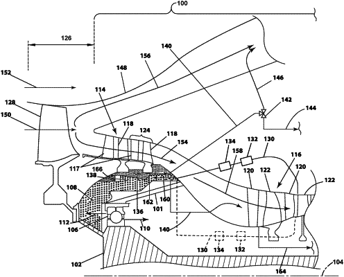
1. A turbine engine comprising:
a drive shaft rotatable about an axis;
a multi-stage compressor section circumscribing and driven by the drive shaft;
a turbine section circumscribing and operably coupled to the drive shaft;
a thrust bearing provided between the drive shaft and at least a portion of the multi-stage compressor section and rotationally supporting the drive shaft;
a balance cavity, located at least partially axially upstream of the thrust bearing, with respect to the axis, and fluidly coupled to at least a portion of the multi-stage compressor section; and
a recoup cavity fluidly coupled to the balance cavity;
wherein during operation of the turbine engine, a first axial force is applied to the thrust bearing in a fore-to-aft direction by the drive shaft, with respect to the axis, and a second axial force is applied by the balance cavity in an opposing direction to the first axial force.
|