| CPC F01N 3/2033 (2013.01) [F01N 9/00 (2013.01); F01N 11/007 (2013.01); F01N 2240/14 (2013.01); F01N 2550/02 (2013.01)] | 11 Claims |

|
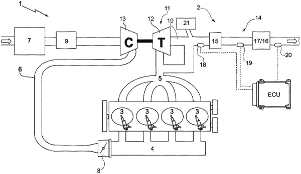
1. A method to control an internal combustion engine (1) provided with an exhaust system (2) for the exhaust gases of a motor vehicle having an exhaust duct (10) and an exhaust gas after-treatment system (14); the method comprises the steps of:
providing at least one catalytic converter (15, 17) arranged along the exhaust duct (10);
providing an oxygen sensor (18, 18*, 18**), that detects an air/fuel ratio of the exhaust gases, said oxygen sensor having an output that indicates a content of oxygen in the exhaust gases;
providing a burner (21), that introduces exhaust gases into the exhaust duct (10) so as to speed up a heating of said at least one catalytic converter (15, 17), wherein inside the burner (21) there is defined a combustion chamber (22), which receives fresh air through an air feeding device (23), which is provided with a pumping device (24) feeding air, and fuel from an injector (27), which is designed to inject fuel into the combustion chamber (22);
providing a spark plug (28) coupled to the burner (21) so as to ignite the mixture present inside the combustion chamber (22);
calculating a thermal power (POBJ) needed to reach a nominal operating temperature of said at least one catalytic converter (15, 17) obtained with an objective value (λOBJ) of the air/fuel ratio;
determining both an objective fuel flow rate (mF_OBJ) and an objective air flow rate (mA_OBJ) to be fed to the burner (21) in order to obtain the thermal power (POBJ) needed to reach the nominal operating temperature of said at least one catalytic converter (15, 17);
determining a nominal number (NNOM) of revolutions with which to operate the pumping device (24) depending on the objective air flow rate (mA_OBJ), on an ambient pressure (PATM), on an ambient temperature (TATM) and on an objective pressure (PA_OBJ) of the air flowing into a shut-off valve (26) that regulates a duct (25) located downstream of the pumping device (24);
determining a closed-loop contribution (NCL) of the number of revolutions with which to operate the pumping device (24) by means of a PID controller, which zeroes a difference between the objective value (λOBJ) of the air/fuel ratio and an actual value (λ) of the air/fuel ratio measured by the oxygen sensor (18, 18*, 18**);
determining a further contribution (NADAT) of the number of revolutions with which to operate the pumping device (24) depending on an integral action of the PID controller under stationary conditions;
determining an actual number (N) of revolutions with which to operate the pumping device (24) by determining the sum of the nominal number (NNOM) of revolutions, of the closed-loop contribution (NCL) of the number of revolutions with which to operate the pumping device (24) and of the further contribution (NADAT) of the number of revolutions with which to operate the pumping device (24); and
signaling a fault when the sum of the first closed-loop contribution (NCL1), the second closed-loop contribution (NCL2) and the further contribution (NADAT) of the number of revolutions with which to operate the pumping device (24) exceeds a predetermined threshold value (THR1).
|