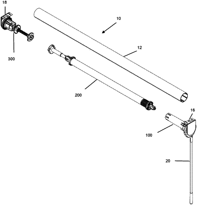
| CPC E06B 9/44 (2013.01) [E06B 9/06 (2013.01); E06B 9/40 (2013.01); E06B 9/50 (2013.01)] | 15 Claims |

|
1. A system for a window covering, comprising:
an elongated tube around which the window covering is able to be wound, the elongate tube being configured to rotate and thereby move the window covering between a retracted position and an extended position;
a clutch assembly disposed at one end of the elongate tube, the clutch assembly comprising:
a pulley;
a power spring, the power spring having a first end engaging the pulley and a second end that is stationary;
a cord arranged at least partially within the clutch assembly, the cord being wound around a perimeter of the pulley; and
a wand fixed to the cord to selectively raise and lower the window covering between the retracted position and the extended position;
the pulley being configured to rotate in a first direction when the wand is pulled downwardly, and to rotate in a second direction that is opposite to the first direction on release of the wand, wherein rotation of the pulley in the second direction is configured to draw the wand upwardly and wind the cord around the perimeter of the pulley, and wherein rotation of the pulley in the first direction causes the elongate tube to rotate in the first direction to move the window covering from the retracted position towards the extended position; and
a booster assembly disposed and hidden from view within the elongate tube, the booster assembly being configured to move the window covering from the extended position towards the retracted position, the booster assembly comprising:
a shaft,
a booster spring disposed around the shaft, the booster spring being configured to apply a rotational force on the elongate tube to move the window covering from the extended position towards the retracted position,
a tube adapter disposed at a first end of the shaft, the tube adapter being engaged with the elongate tube,
a damper disposed at a second end of the shaft, the damper being configured to provide damping to the elongate tube when the window covering moves from the extended position towards the retracted position,
a position stop jacket engaging a first end of the booster spring, and
a position stop track member that provides a locking function for the booster assembly, the position stop track member being disposed in the position stop jacket, the position stop track member comprising a plurality of tracks and a ball bearing disposed in the tracks of the stop track member, the tracks and the ball bearing being configured to cooperate to form a barrel cam, the tracks comprising a plurality of positions for locking the booster assembly and a plurality of positions for releasing the booster assembly.
|