| CPC C08G 64/205 (2013.01) [B01F 27/1134 (2022.01); B01F 27/86 (2022.01); B01F 27/91 (2022.01); B01J 19/0013 (2013.01); B01J 19/0066 (2013.01); C08G 64/305 (2013.01); B01F 2101/2204 (2022.01); B01F 2215/0422 (2013.01); B01F 2215/0431 (2013.01); B01F 2215/0459 (2013.01); B01F 2215/0481 (2013.01); B01J 2219/00768 (2013.01); B01J 2219/1943 (2013.01)] | 20 Claims |

|
1. A reactor for carrying out a melt transesterification reaction at a reactor temperature of 160 to 300° C. and a reactor pressure of 5 to 200 mbar, comprising:
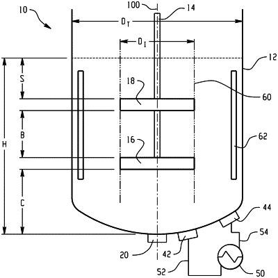
a cylindrical tank comprising a top, a side, and a bottom, wherein the bottom is convex, extending away from the top;
a stirring shaft disposed within the cylindrical tank along an axis thereof so that it is rotatable from outside of the cylindrical tank;
an impeller extending from the stirring shaft in the cylindrical tank and comprising a plurality of blades that are each independently at an angle α from an orthogonal of the axis;
a reactant solution inlet;
a reaction solution outlet; and
an externally located heat exchanger in fluid communication with the cylindrical tank via a recirculation stream and a heated stream,
wherein the reactor comprises at least one of
i) a lower impeller and an upper impeller extending from the stirring shaft, wherein the lower impeller and the upper impeller are both three blade impellers and the lower impeller and the upper impeller are offset by an angle θ of 50 to 70 degrees,
ii) a lower impeller and an upper impeller extending from the stirring shaft, wherein the lower impeller and the upper impeller are both three blade impellers and the angle α of the blades of the lower impeller and the angle α of the upper impeller are each independently 25 to 65 degrees, and
iii) a ratio of C:DI of 0.05 to 0.5 and a ratio of S:DI of 0.1 to 2, wherein C is a length from a lowest point in the cylindrical tank to a lowest point on the impeller; DI is two times the length of a blade of the impeller; and S is a length from a level fluid line to a highest point of the impeller.
|