| CPC C03B 25/08 (2013.01) [C03B 27/0404 (2013.01); C03B 27/044 (2013.01)] | 13 Claims |
|
1. A device for annealing a glass pane, the device comprising:
a plurality of rollers on which the glass pane can be transported horizontally,
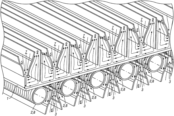
a plurality of first cooling air feeds running parallel to axes of the rollers, from which cooling air can be guided onto an underside of the glass pane, each of the first cooling air feeds being arranged between two of the rollers;
a plurality of second cooling air feeds running parallel to the axes of the rollers, from which cooling air can be guided onto a top surface of the glass pane, each of the second cooling air feeds being arranged above the glass pane, and each of the first and second cooling air feeds extending over a width of the glass pane; and
upper partitions arranged on both parallel sides of each of the second cooling air feeds, wherein the rollers form lower partitions and are arranged on both parallel sides of each of the first cooling air feeds, and
the upper partitions being a flat wall with a thickness of the flat wall is less than a diameter of the roller and extending to a distance of no more than 10 mm from the glass pane,
and with each of the first and second cooling air feeds being formed as a nozzle having a slit with the nozzle becoming increasingly narrow in the direction toward to glass pane so as to form a flow channel extending over the width of the glass pane that continuously tapers to where the cooling air emerges from the flow channel, such that the cooling air from each of the first cooling air feeds strikes the underside of the glass pane, is deflected outward to both sides toward the rollers forming the lower partitions, and then strikes the rollers and is diverted downward such that return of this cooling air deflected from the glass pane occurs between the rollers forming the lower partitions and outer sides of the continuous tapering flow channel at the first cooling air feed,
and the cooling air from each of the second cooling air feeds strikes the top surface of the glass pane, is deflected outward to both sides toward the flat walls forming the upper partitions, and then strikes the flat walls and is diverted upward such that return of this cooling air deflected from the glass pane occurs between the flat walls forming the upper partitions and outer sides of the continuous tapering flow channel of the second cooling air feed.
|