| CPC B65B 13/025 (2013.01) [B25B 25/00 (2013.01); B65B 13/22 (2013.01); B65B 13/285 (2013.01); E04G 21/123 (2013.01)] | 9 Claims |

|
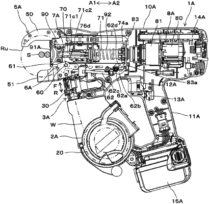
1. A binding machine comprising:
a wire feeding unit configured to feed a wire;
a curl forming unit configured to form a path along which the wire fed by the wire feeding unit is to be wound around a to-be-bound object;
a butting part against which the to-be-bound object is to be butted;
a cutting unit configured to cut the wire wound on the to-be-bound object;
a binding unit configured to twist the wire wound on the to-be-bound object and cut by the cutting unit, the binding unit comprising:
a rotary shaft,
a wire engaging body configured to move in an axis direction of the rotary shaft, to engage the wire and to twist the wire with rotating together with the rotary shaft, and
a spring for urging the rotary shaft in a direction in which the wire engaging body gets away from the butting part along the axis direction of the rotary shaft, and for regulating an axial position of the rotary shaft; and
a tension applying part, separate from the spring, configured to apply tension to the wire to be cut at the cutting unit with a force higher than a reaction force of the wire in a loosening direction of the wire wound on the to-be-bound object.
|