| CPC B63H 1/22 (2013.01) [B63G 8/08 (2013.01); B63H 21/21 (2013.01); B63H 23/34 (2013.01); B63G 2008/004 (2013.01); B63H 2021/216 (2013.01)] | 15 Claims |

|
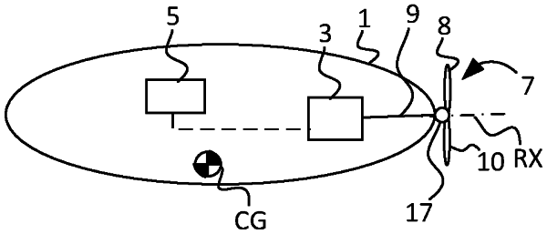
1. A watercraft vehicle (1) comprising:
a drive motor arrangement (3) coupled to a control circuitry (5) configured for manoeuvring the watercraft vehicle (1);
a propeller shaft (9) coupled between the drive motor arrangement (3) and a propeller assembly (7) forming a propeller disc (11) during rotation of said propeller shaft (9) about an axis of rotation (RX); and
a hub member (17) of the propeller shaft (9) coupled to the propeller assembly (7),
wherein:
a first propeller blade (8) of the propeller assembly (7) is hingedly coupled to a first oblique lag-pitch hinge (22′) of the hub member (17);
a second propeller blade (10) of the propeller assembly (7) is hingedly coupled to a second oblique lag-pitch hinge (22″) of the hub member (17);
a first oblique axis (21′) of the first oblique lag-pitch hinge (22′) is oriented in a direction oblique to the axis of rotation (RX);
a second oblique axis (21″) of the second oblique lag-pitch hinge (22″) is oriented in a direction oblique to the axis of rotation (RX) and parallel with the first oblique axis (21″);
the control circuitry (5) is configured to provide a first drive thrust (T′) in a first arc segment (13′) of the propeller disc (11) and to provide a second drive thrust (T″) in a second arc segment (13″) of the propeller disc (11) by controlling a rate of change of the rotational velocity of the propeller shaft (9);
a first propeller blade pitch change is achieved about the first oblique axis (21′); and
a second propeller blade pitch change is achieved about the second oblique axis (21″).
|