| CPC B60L 50/64 (2019.02) [H01M 50/209 (2021.01); H01M 50/224 (2021.01); H01M 50/242 (2021.01); H01M 50/249 (2021.01); H01M 50/264 (2021.01); B60K 6/28 (2013.01); B60Y 2200/92 (2013.01); B60Y 2400/112 (2013.01); H01M 2220/20 (2013.01)] | 10 Claims |

|
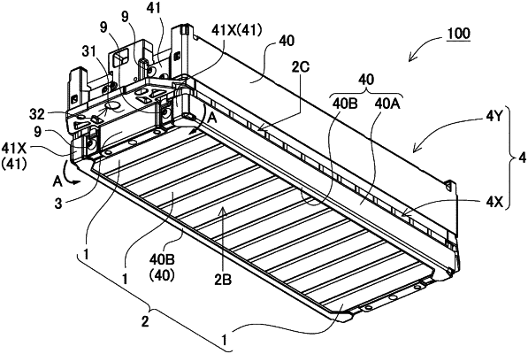
1. A power supply device comprising:
a battery stack where a plurality of battery cells are stacked;
a pair of end plates that are disposed at both end portions of the battery stack; and
a bind bar that extends in a stacking direction of the plurality of battery cells of the battery stack and has both end portions coupled to the end plates,
wherein the battery stack is a quadrangular prism extending in the stacking direction of the battery cells, and has four surrounding surfaces including an electrode surface where sealing plates of the plurality of battery cells are disposed on a same plane, a bottom surface on an opposite side of the electrode surface, and facing side surfaces where the bind bar is disposed,
the bind bar is divided in a width direction of the facing side surfaces, and each of the divided bind bars includes a bent piece that is fixed and attached to a surface of one of the pair of end plates,
at least one of the divided bind bars further includes a bent piece fixed with a single bolt, the bent piece being fixed to the one of the pair of end plates via one bolt,
the one of the pair of end plates includes a stopper wall where an outer peripheral edge of the bent piece fixed with the single bolt is fitted to prevent rotation,
the bent piece fixed with the single bolt is in contact with the stopper wall to be fixed to the pair of one of the end plates in a state where the rotation is prevented,
the one of the pair of end plates includes a planar projecting surface extending from an upper edge of the stopper wall and projecting in the stacking direction away from an outer surface of the one of the pair of end plates, and
the bent piece of the bind bar includes:
a fixing portion configured to be bolted to the outer surface of the one of the pair of end plates, and
a stopper protrusion projecting in the stacking direction away from the fixing portion, the stopper protrusion including:
a cover plate configured to overlap the planar projecting surface in the stacking direction, and
a peripheral wall portion of the cover plate configured to oppose the stopper wall in a direction perpendicular to the stacking direction.
|