| CPC B05B 11/104 (2023.01) [A47J 41/0033 (2013.01); B05B 11/1047 (2023.01); B05B 11/1059 (2023.01)] | 54 Claims |

|
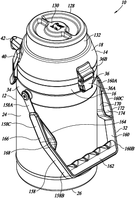
1. An airpot beverage dispenser for dispensing a beverage, comprising:
a container body with a body upper end portion and a beverage cavity for holding the beverage;
a lid attachable to the body upper end portion, the lid including:
a lower lid portion in fluid tight sealing engagement with the body upper end portion, and having a lower lid upper wall with first and second apertures; and
an upper lid portion having an upwardly open upper lid portion chamber with a chamber sidewall and a chamber bottom wall having a chamber bottom wall aperture;
a spout including:
a spout head portion having an outward end portion with an opening for dispensing the beverage contained in the beverage cavity, and an inward end portion; and
a spout conduit having an upper end portion in fluid communication with the inward end portion of the spout head portion and a lower end portion positioned within the beverage cavity, at least one of the inward end portion of the spout head portion and an upper end portion of a spout feed conduit extending through the first aperture of the lower lid upper wall and being in fluid tight sealing engagement with the lower lid portion;
a bellows positioned at least partially within the upper lid portion chamber, the bellows having an upper bellows end wall with an upper bellows aperture, and a lower bellows end wall with a lower bellows aperture;
a bellows spring having an upper spring end portion and a lower spring end portion, the lower spring portion being positioned within the bellows and having a lower end in engagement with the lower bellows end wall, and the upper spring end portion extending through the upper bellows aperture and having an upper end positioned above the upper bellows end wall;
a manually operable actuator positioned at least partially within the upper lid portion chamber for reciprocal movement therein, the actuator having a top wall portion positioned above the upper bellows end wall and a sidewall extending downward from the top wall and into the upper lid portion chamber, the top wall being in engagement with the upper end of the upper spring end portion, the actuator being downwardly movable between an upper first position, a second position below the upper first position, a third position below the second position, and a fourth position below the third position, the top wall portion of the actuator being in engagement with the upper bellows end wall during downward movement of the actuator between the second position and the fourth position and applying a downward force on the upper bellows end wall to progressively collapse the bellows;
an upper valve including an upper seal and an upper seat, the upper seal being positioned to close the upper bellows aperture when the actuator is moved downward from the first position to the second position whereat the upper seal is in fluid tight sealing engagement with the upper seat and prevents air in the bellows from escaping out the upper bellows aperture, thereby trapping air in the bellows, one of the upper seal and the upper seat being attached to the actuator and the other being attached to the upper bellows end wall; and
a valve assembly supported by the lower bellows end wall for upward and downward movement therewith, the valve assembly including:
a skirt valve portion having a skirt wall with an upper end skirt wall portion and a flexible lower end skirt wall portion, the lower end skirt wall portion defining a skirt wall aperture, when the actuator is moved downward to the third position, the lower end skirt wall portion is positioned in fluid tight sealing engagement with the lower lid upper wall and extends fully about the second aperture of the lower lid upper wall, downward movement of the actuator from the second position to the third position at least partially collapsing the bellows and thereby increasing the pressure of the trapped air in the bellows; and
a duckbill valve portion having an upper duckbill valve portion and a lower duckbill valve portion, the upper duckbill valve portion being in fluid communication with the lower bellows aperture, the upper end skirt wall portion being in fluid tight sealing engagement with the upper duckbill valve portion and the lower end skirt wall portion extending fully about the lower duckbill valve portion, the lower duckbill valve portion having first and second sidewalls with a normally closed slit extending between the first and second sidewalls, downward movement of the actuator from the third position to the fourth position further collapses the bellows and thereby further increases the pressure of the trapped air in the bellows, when the actuator is in the fourth position, the pressure of the trapped air is sufficient to separate the first and second sidewalls and thereby open the slit and provide a fluid passageway for the trapped air in the bellows to the beverage cavity through the second aperture of the lower lid upper wall, thereby the duckbill valve portion serves as a one-way valve only permitting outward flow of the pressurized trapped air in the bellows to pass from the lower bellows aperture through the chamber bottom wall aperture into the beverage cavity through the second aperture of the lower lid upper wall, the pressurized trapped air provided to the beverage cavity being sufficient to force a portion of the beverage in the beverage cavity into the spout conduit and upward into the spout head and to be dispensed out of the opening of the outward end portion of the spout head.
|