| CPC A62C 31/05 (2013.01) [A62C 99/0018 (2013.01); F15B 21/008 (2013.01)] | 23 Claims |

|
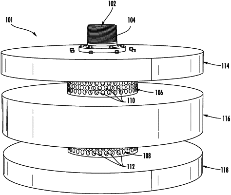
1. A fire suppression nozzle, comprising:
a first conduit comprising an inlet and an outlet;
a second conduit coupled to the first conduit and comprising a first plurality of outlets spaced apart from a second plurality of outlets along a length of the second conduit by a middle portion of the second conduit with no outlets, wherein the first plurality of outlets and the second plurality of outlets connect directly to an environment surrounding the nozzle;
a first circular sound absorbing member positioned on a first side of the outlet; and
a second circular sound absorbing member positioned on a second side of the outlet;
wherein each of the first circular sound absorbing member and the second circular sound absorbing member comprise:
a support plate; and
a sound absorbing insert, wherein the sound absorbing insert is composed of a sound absorbing material;
wherein the first conduit is configured to receive an inert gas at the inlet and provide the inert gas to an interior of the second conduit via the outlet at a location between a first end of the second conduit and a second end of the second conduit, wherein the location is aligned with the middle portion;
wherein the first conduit and the second conduit are configured such that the inert gas exits the outlet in a first direction and a first portion of the inert gas is directed toward the first plurality of outlets in a second direction, and a second portion of the inert gas is directed toward the second plurality of outlets in a third direction opposite the second direction, wherein the second and third directions are generally perpendicular to the first direction, and
wherein a first flow rate of the first portion of the inert gas and a second flow rate of the second portion of the inert gas are substantially equal.
|