| CPC A61F 9/00804 (2013.01) [A61B 3/1025 (2013.01); A61B 3/14 (2013.01); A61F 9/008 (2013.01); A61F 9/00802 (2013.01); A61F 9/00812 (2013.01); A61F 9/00836 (2013.01); A61F 2009/00846 (2013.01); A61F 2009/00855 (2013.01); A61F 2009/00868 (2013.01); A61F 2009/00872 (2013.01); A61F 2009/00889 (2013.01); A61F 2009/00897 (2013.01)] | 15 Claims |

|
1. A method of performing laser eye surgery on a patient's eye while accommodating patient movement, the method comprising:
by a laser beam source, generating a laser beam;
by an objective lens, focusing the laser beam to a focal point in the eye;
by a scanning assembly, supporting the objective lens and scanning the focal point of the laser beam to different target locations within the eye in an xy-plane and a z direction, x, y and z being three orthogonal directions;
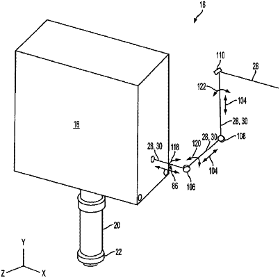
by a free-floating mechanism, supporting the scanning assembly and accommodating free movement of the scanning assembly relative to the laser beam source in the x, y and z directions in response to external forces exerted on the objective lens or the scanning assembly, while maintaining alignment in the x, y and z directions between the laser beam and the target locations during the free movement, including:
sliding first and second beam deflection devices of the free-floating mechanism relative to one another to vary a distance between the first and second beam deflection devices, the first and second beam deflection devices being external to the scanning assembly and located on an optical path between the laser beam source and the scanning assembly;
by the first beam deflection device, receiving the laser beam in a first direction and deflecting it to a second direction; and
by the second beam deflection device, receiving the laser beam in the second direction and deflecting it to a third direction, wherein one of the first, second and third directions is the z direction, another one of the first, second and third directions is the x direction, and yet another one of the first, second and third directions is the y direction;
by the second beam deflection device, receiving a reflection of a portion of the laser beam from a location of the focal point propagating in a direction opposite to the third direction and deflecting it to a direction opposite to the second direction;
by the first beam deflection device, receiving the portion of the electromagnetic radiation beam propagating in the direction opposite to the second direction and deflecting it to a direction opposite to the first direction; and
by a detection assembly, receiving the reflection of the portion of the laser beam and generating an intensity signal indicative of an intensity of the reflection of the portion of the laser beam.
|