| CPC A61B 17/1624 (2013.01) [A61B 17/1626 (2013.01); A61B 17/1628 (2013.01); A61B 17/162 (2013.01); A61B 17/1622 (2013.01); A61B 17/1671 (2013.01); A61B 17/32002 (2013.01); A61B 2017/00398 (2013.01); A61B 2017/00734 (2013.01); A61B 2017/320028 (2013.01)] | 10 Claims |

|
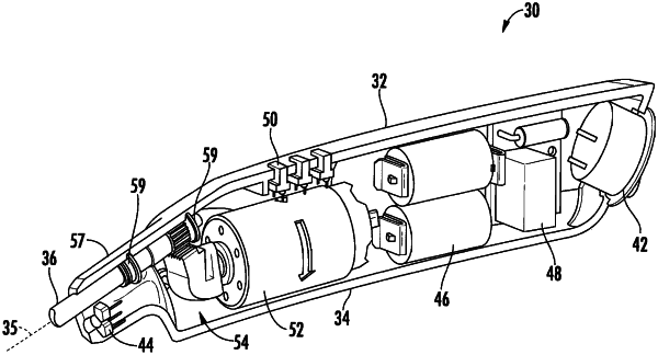
1. A rotary oscillating surgical tool comprising:
a housing having an outer surface suitable for use as a handle for manually gripping the tool,
a motor suitably mounted in the housing so that a rotor portion of the motor is free to rotate to drive a motor shaft, a stator portion of the motor being fixed against rotation in the housing,
a transmission, is positioned in the housing and operably couples the motor shaft to the cutter shaft, the transmission comprises a first section operable to convert the continuous rotary motion of the motor shaft of the motor to reciprocating linear motion of a portion thereof, and a second section is operable to convert that reciprocating linear motion to oscillating rotary motion, the oscillating rotary motion transferred to the cutter shaft therein causing a cutter to oscillate in a rotary manner about a longitudinal axis of the cutter,
wherein the transmission includes an internal toothed ring gear suitably fixed in the housing to prevent its motion relative to the housing, a pinion gear, positioned inside of and having its external gear teeth in engagement with the internal gear teeth of the ring gear, the pinion gear suitably mounted to a crank arm, which in turn is secured to the motor shaft of the motor and is offset from the axis of rotation of the motor shaft, so that the pinion gear revolves about the axis of rotation of the motor shaft while inside the ring gear,
wherein the crank arm has a counterweight secured on an opposite side of the longitudinal axis of the motor shaft with respect to where the pinion gear is mounted to the crank arm,
a driver arm secured to the pinion gear extending forwardly of the ring gear for receipt in a follower to effect movement of the follower in response to movement of the driver arm, the follower is suitably mounted in the housing in a manner to permit its pivoting movement about an axle, the follower is provided with a sector gear, that is operably coupled to a driven gear member secured to the cutter shaft so that as the follower moves, the cutter shaft moves in response thereto by engagement between the sector gear 76 and the driven gear member,
wherein the cutter shaft is positioned at an angle with respect to the longitudinal axis of the housing.
|