| CPC A61B 17/068 (2013.01) [A61B 17/00234 (2013.01); A61B 17/0684 (2013.01); A61B 17/072 (2013.01); A61B 17/07207 (2013.01); A61B 17/105 (2013.01); A61B 17/32 (2013.01); A61B 17/320068 (2013.01); A61B 34/30 (2016.02); A61B 18/1445 (2013.01); A61B 50/30 (2016.02); A61B 50/36 (2016.02); A61B 2017/00115 (2013.01); A61B 2017/00314 (2013.01); A61B 2017/00323 (2013.01); A61B 2017/00367 (2013.01); A61B 2017/00398 (2013.01); A61B 2017/00473 (2013.01); A61B 2017/00477 (2013.01); A61B 2017/00685 (2013.01); A61B 2017/00734 (2013.01); A61B 2017/0688 (2013.01); A61B 2017/07257 (2013.01); A61B 2017/07271 (2013.01); A61B 2017/07278 (2013.01); A61B 2017/07285 (2013.01); A61B 2017/2905 (2013.01); A61B 2017/2923 (2013.01); A61B 2017/2927 (2013.01); A61B 2017/2933 (2013.01); A61B 2017/2937 (2013.01); A61B 2017/2943 (2013.01); A61B 2017/320069 (2017.08); A61B 2017/320071 (2017.08); A61B 2018/1455 (2013.01); A61B 2034/302 (2016.02); A61B 2090/0811 (2016.02); Y10T 29/53 (2015.01)] | 18 Claims |

|
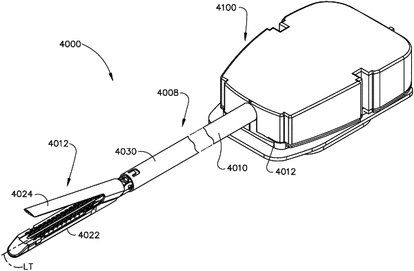
1. A robotic surgical stapling device for use with a surgical robot, the robotic surgical stapling device comprising:
an end effector, comprising:
a first jaw; and
a second jaw movable relative to the first jaw from an open configuration toward a closed configuration;
a shaft extending proximally from the end effector;
a first rotary interface releasably coupleable to the surgical robot;
a first cable coupled to the first rotary interface, wherein the first cable is movable by the first rotary interface to articulate the end effector relative to the shaft about a first axis;
a second rotary interface releasably coupleable to the surgical robot;
a second cable coupled to the second rotary interface, wherein the second cable is movable by the second rotary interface to articulate the end effector relative to the shaft about a second axis;
a third rotary interface releasably coupleable to the surgical robot, wherein the third rotary interface is configured to drive the end effector from the open configuration to the closed configuration;
a firing assembly driveable by the third rotary interface, wherein the firing assembly comprises:
a firing member, comprising:
a first camming portion configured to engage the first jaw; and
a second camming portion configured to engage the second jaw; and
a composite drive extending proximally from the firing member, wherein the composite drive is driven by the third rotary interface, and wherein the composite drive comprises:
a cable portion; and
a firing bar, wherein the cable portion is coupled to the firing bar proximal to the firing member, wherein the cable portion and the firing bar are configured to cooperatively advance the firing member during a firing stroke, and wherein the cable portion and the firing bar are configured to cooperatively retract the firing member to permit a transition of the second jaw toward the open configuration; and
a gear mechanism selectively engageable with the firing assembly intermediate the firing member and the third rotary interface.
|